XMLWriter

We assume you have already learned what is described in:
If you want to find the appropriate Writer for your purpose, see Writers Comparison.
Short Summary
XMLWriter formats records into XML files.
| Component | Data output | Input ports | Output ports | Transformation | Transf. required | Java | CTL |
|---|---|---|---|---|---|---|---|
| XMLWriter | XML file | 1-n | 0-1 | no | no | no | no |
Abstract
XMLWriter receives input data records, joins them and formats them into a user-defined XML structure. Even complex mapping is possible and thus the component can create arbitrary nested XML structures.
XMLWriter combines streamed and cached data processing depending on the complexity of the XML structure. This allows to produce XML files of arbitrary size in most cases. However, the output can be partitioned into multiple chunks - i.e. large difficult-to-process XML files can be easily split into multiple smaller chunks.
Standard output options are available: files, compressed files, the console, an output port or a dictionary.
The component needs Eclipse v. 3.6 or higher to run.
Icon
Ports
| Port type | Port number | Required | Description | Metadata |
|---|---|---|---|---|
| Input | 0-N | At least one | Input records to be joined and mapped into an XML file | Any (each port can have different metadata) |
| Output | 0 | no | For port writing, see Writing to Output Port. | One field (byte,
cbyte, string). |
XMLWriter Attributes
| Attribute | Req | Description | Possible values |
|---|---|---|---|
| Basic | |||
| File URL | yes | The target file for the output XML. See Supported File URL Formats for Writers. | |
| Charset | The encoding of an output file generated by XMLWriter. | ISO-8859-1 (default) | <other encodings> | |
| Mapping | 1) | Defines how input data is mapped onto an output XML. See Advanced Description for more information. | |
| Mapping URL | 1) | External text file containing the mapping definition. See Creating the Mapping - Mapping Ports and Fields. and Creating the Mapping - Source Tab. for the mapping file format. Put your mapping to an external file if you want to share a single mapping among multiple graphs. | |
| XML Schema | The path to an XSD schema. If
XML Schema is set,
the whole mapping can be automatically pre-generated from the schema.
To learn how to do it, see Creating the Mapping - Using Existing XSD Schema
.
The schema has to be placed in the meta folder.
| none (default) | any valid XSD schema | |
| Advanced | |||
| Create directories | If true, non existing directories included in
the File URL path will be automatically created.
| false (default) | true | |
| Omit new lines wherever possible | By default, each element is written to a separate line.
If set to true, new lines are omitted when
writing data to the output XML structure. Thus, all XML
tags are on one line only.
| false (default) | true | |
| Directory for temporary files | Select a path to a directory where temporary files created during the mapping are stored. | (default system temp directory) | any other directory | |
| Cache size | A size of of the database used when caching data from ports to elements (the data is first processed then written). The larger your data is, the larger cache is needed to maintain fast processing. | default: auto | e.g. 300MB, 1GB etc. | |
| Sorted input | Tells XMLWriter whether the input data is sorted. Setting the attribute to true declares you want to use the sort order defined in Sort keys, see below. | false(default)|true | |
| Sort keys | Tells XMLWriter how the input data is sorted, thus enabling streaming (see Creating the Mapping - Mapping Ports and Fields ). The sort order of fields can be given for each port in a separate tab. Working with Sort keys has been described in Sort Key. | ||
| Records per file | Maximum number of records that are written to a single file. See Partitioning Output into Different Output Files | 1-N | |
| Max number of records | Maximum number of records written to all output files. See Selecting Output Records. | 0-N | |
| Partition key | A key whose values control the distribution of records among multiple output files. See Partitioning Output into Different Output Files for more information. | ||
| Partition lookup table | The ID of a lookup table. The table serves for selecting records which should be written to an output file(s). See Partitioning Output into Different Output Files for more information. | ||
| Partition file tag | By default, output files are numbered. If this attribute is set to
Key file tag, output files are named
according to the values of Partition key
or Partition output fields. See Partitioning Output into Different Output Files for more
information. | Number file tag (default) | Key file tag | |
| Partition output fields | Fields of Partition lookup table whose values serve for naming output file(s). See Partitioning Output into Different Output Files for more information. | ||
| Partition unassigned file name | The name of a file that the unassigned records should be written into (if there are any). If it is not given, the data records whose key values are not contained in Partition lookup table are discarded. See Partitioning Output into Different Output Files for more information. | ||
Legend:
1) One of these attributes has to be specified. If both are defined, Mapping URL has a higher priority.
Advanced Description
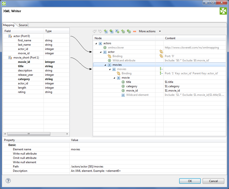
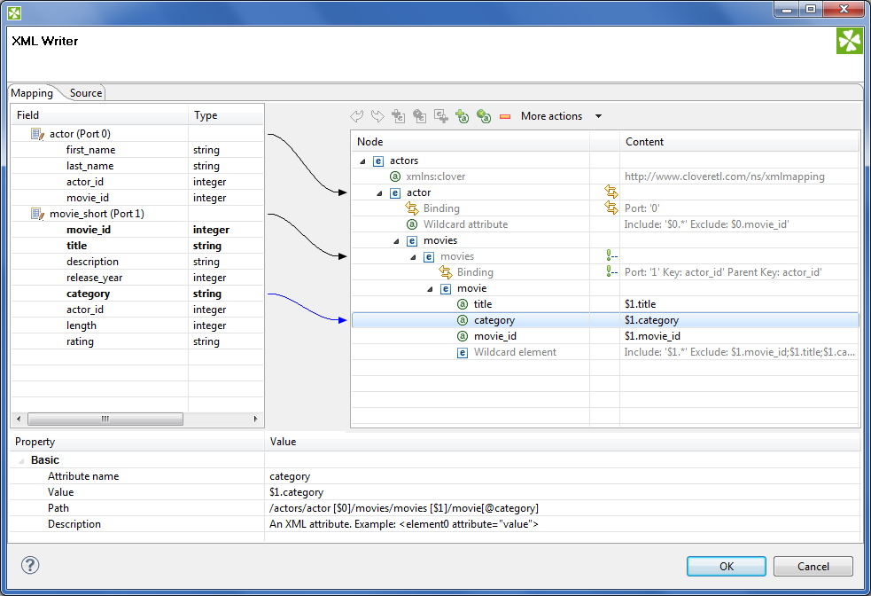
XMLWriter's core part is the mapping editor that lets you visually map input data records onto an XML tree structure (see Figure 54.12, “Mapping Editor”). By dragging the input ports or fields onto XML elements and attributes you map them, effectively populating the XML structure with data.
What is more, the editor gives you direct access to the mapping source where you can virtually edit the output XML file as text. You use special directives to populate the XML with CloudConnect data there (see Figure 54.20, Source tab in Mapping editor.).
The XML structure can be provided as an XSD Schema (see the XML Schema attribute) or you can define the structure manually from scratch.
You can access the visual mapping editor clicking the "..." button of the Mapping attribute.
When inside the editor, notice its two main tabs in the upper left corner of the window:
Mapping - enables you to design the output XML in a visual environment
Source - that is where you can directly edit the XML mapping source code
Changes made in the Mapping tab take immediate effect in the Source tab and vice versa. In other words, both editor tabs allow making equal changes.
When you switch to the Mapping tab, you will notice there are three basic parts of the window:
Left hand part with Field and Type columns - represents ports of the input data. Ports are represented by their symbolic names in the Field column. Besides the symbolic name, ports are numbered starting from $0 for the first port in the list. Underneath each port, there is a list of all its fields and their data types. Please note neither port names, field names nor their data types can be edited in this section. They all depend merely on the metadata on the XMLWriter's input edge.
Right hand part with Node and Content columns - the place where you define the structure of output elements , attributes , wildcard elements or wildcard attributes and namespaces. In this section, data can be modified either by double-clicking a cell in the Node or the Content column. The other option is to click a line and observe its Property in the bottom part section of the window.
Bottom part with Property and Value columns - for each selected Node, this is where its properties are displayed and modified.
Creating the Mapping - Designing New XML Structure
The mapping editor allows you to start from a completely blank mapping - first designing the output XML structure and then mapping your input data to it. The other option is to use your own XSD schema, see Creating the Mapping - Using Existing XSD Schema.
As you enter a blank mapping editor, you can see input ports on the left hand side and a root element on the right hand side. The point of mapping is first to design the output XML structure on the right hand side (data destination). Second, you need to connect port fields on the left hand side (data source) to those pre-prepared XML nodes (see Creating the Mapping - Mapping Ports and Fields).
Let us now look on how to build a tree of nodes the input data will flow to. To add a node, right-click an element, click or Add Property and select one of the available options:
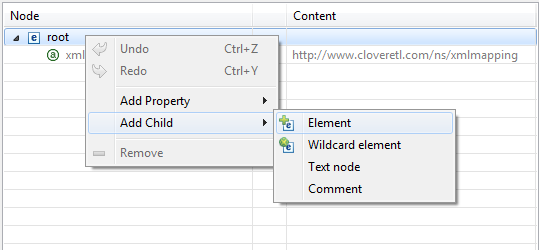
![[Important]](figures/important.png) | Important |
|---|---|
For a closer look on adding nodes, manipulating them and using smart drag and drop mouse techniques, see Working with Nodes. |
Namespace
Adds a Namespace as a new xmlns:prefix
attribute of the selected element.
Declaring a Namespace allows you to use your own
XML tags. Each Namespace consists of a prefix and an URI. In case of XMLWriter mapping,
the root element has to declare the cloudconnect namespace, whose URI
is http://www.cloudconnect.com/ns/xmlmapping. That grants you access to all special
XML mapping tags. If you switch to the Source tab,
you will easily recognise those tags as they are distinct by starting with cloudconnect:, e.g.
cloudconnect:inport="2". Keep in mind that no XML tag beginning with the cloudconnect:
prefix is actually written into the output XML.
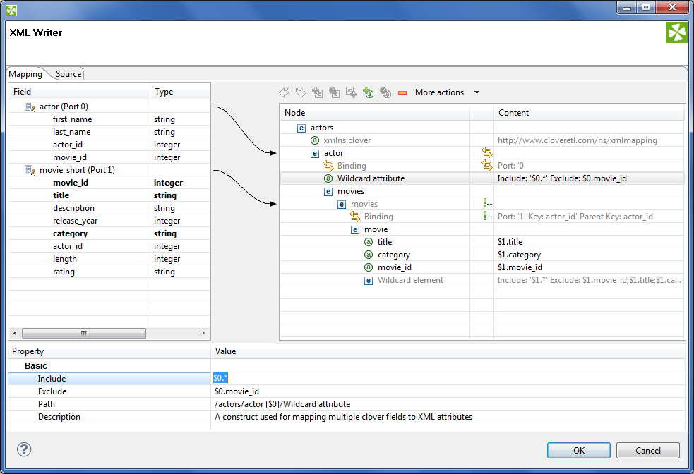
Wildcard attribute
Adds a special directive to populate the element with attributes based on Include / Exclude wildcard patterns instead of mapping these attributes explicitly. This feature is useful when you need to retain metadata independence.
Attribute names are generated from field names of the respective metadata. Syntax: use
$portNumber.field or $portName.field
to specify a field, use * in the field name for "any string". Use ; to specify multiple patterns.
Example 54.2. Using Expressions in Ports and Fields
$0.* - all fields on port 0
$0.*;$1.* - all fields on ports 0 and 1 combined
$0.address* - all fields beginning with the "address" prefix, e.g. $0.addressState,
$0.addressCity, etc.
$child.* - all fields on port child (the port is denoted by its name
instead of an explicit number)
There are two main properties in a Wildcard attribute. At least one of them has to be always set:
Include - defines the inclusion pattern, i.e. which fields should be included in the automatically generated list. That is defined by an expression whose syntax is
$port.field. A good use of expressions explained above can be made here. Include can be left blank provided Exclude is set (and vice versa). If Include is blank, XMLWriter lets you use all ports that are connected to nodes up above the current element (i.e. all its parents) or to the element itself.Exclude - lets you specify the fields that you explicitly do not want in the automatically generated list. Expressions can be used here the same way as when working with Include.
Example 54.3. Include and Exclude property examples
1. Include =
$0.i*Exclude =
$0.indexInclude takes all fields from port $0 starting with the 'i' character. Exclude then removes the
indexfield of the same port.2. Include = (blank)
Exclude =
$1.*;$0.idInclude is not given so all ports connected to the node or up above are taken into consideration. Exclude then removes all fields of port $1 and the
idfield of port $0. Condition: ports $0 and $1 are connected to the element or its parents.
Attribute
Adds a single attribute to the selected element. Once done, the Attribute name can be changed either by double-clicking it or editing Attribute name at the bottom. The attribute Value can either be a fixed string or a field value that you map to it. You can even combine static text and multiple field mappings. See example below.
Example 54.4. Attribute value examples
Film - the attribute's value is set to the literal string "Film"
$1.category - the category field of port $1 becomes the
attribute value
ID: '{$1.movie_id}' -
produces "ID: '535'", "ID: '536'" for movie_id field
values 535 and 536 on port $1. Please note the curly brackets that can
optionally delimit the field identifier.
Path and Description are common properties for most nodes. They both provide a better overview for the node. In Path, you can observe how deep in the XML tree a node is located.
Element
Adds an element as a basic part of the output XML tree.
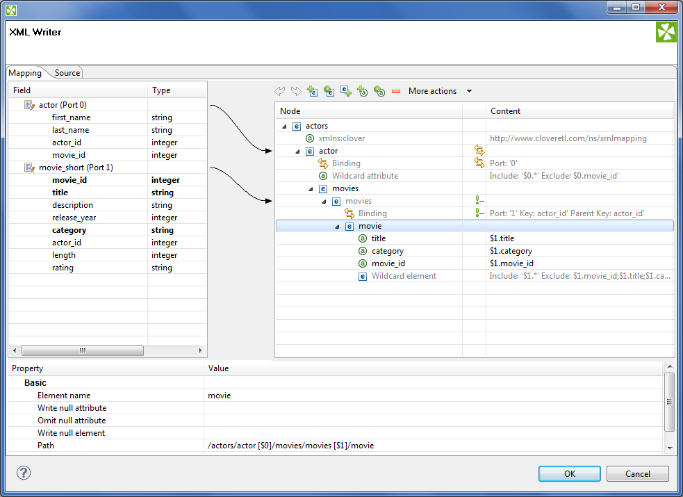
Depending on an element's location in the tree and ports connected to it, the element can have these properties:
Element name - name of the element as it will appear in the output XML.
Value - element value. You can map a field to an element and it will populate its value. If on the other hand you map a port to an element, you will create a Binding (see Creating the Mapping - Mapping Ports and Fields). If Value is not present, right-click the element and choose Add Child - Text node. The element then gets a new field representing its text value. The newly created Text node cannot be left blank.
Write null attribute - by default, attributes with values mapping to NULL will not be put to the output. However, here you can explicitly list names of attributes that will always appear in the output.
Example 54.5. Writing null attribute
Let us say you have an element <date> and its attribute "time" that maps to input port 0, field
time(i.e. <date time="$0.time"/>). For records where thetimefield is empty (null), the default output would be:<date/>Setting Write null attribute to
timeproduces:<date time="" />Omit null attribute - in contrast to Write null attribute, this one specifies which of the current element's attributes will NOT be written if their values are null. Obviously, such behaviour is default. The true purpose of Omit null attribute lies in wildcard expressions in combination with Write null attribute.
Example 54.6. Omitting Null Attribute
Let us say you have an element with a Wildcard attribute. The element is connected to port 2 and its fields are mapped to the wildcard attribute, i.e. Include=$2.*. You know that some of the fields contain no data. You would like to write SOME of the empty ones, e.g.
heightandwidth. To achieve that, click the element and set:Write null attribute=$2.* - forces writing of all attributes although they are null
Omit null attribute=$2.height;$2.width - only these attributes will not be written
Hide - in elements having a port connected, set Hide to
trueto force the following behaviour: the selected element is not written to the output XML while all its children are. By default, the property is set tofalse. Hidden elements are displayed with a grayish font in the Mapping editor.Example 54.7. Hide Element
Imagine an example XML:
<address>
	<city>Atlanta</city>
	<state>Georgia</state>
</address>
<address>
	<city>Los Angeles</city>
	<state>California</state>
</address>
Then hiding the
addresselement produces:<city>Atlanta</city> <state>Georgia</state> <city>Los Angeles</city> <state>California</state>
Partition - by default, partitioning is done according to the first and topmost element that has a port connected to it. If you have more such elements, set Partition to
truein one of them to distinguish which element governs the partitioning. Please note partitioning can be set only once. That is if you set an element's Partition totrue, you should not set it in either of its subelements (otherwise the graph fails). For a closer look on partitioning, see Partitioning Output into Different Output Files.Example 54.8. Partitioning According to Any Element
In the mapping snippet below, setting Partition to
trueon the <invoice> element produces the following behaviour:<person> will be repeated in every file
<invoice> will be divided (partitioned) into several files
<person cloudconnect:inPort="0">
	<firstname> </firstname>
	<surname> </surname>
</person>

<invoice cloudconnect:inPort="1" cloudconnect:partition="true""">
	<customer> </customer>
	<total> </total>
</invoice>
Wildcard element
Adds a set of elements. The
Include and Exclude properties influence
which elements are added and which not. To learn how to make use of the $port.field
syntax, please refer to Wildcard attribute. Rules and examples described
there apply to Wildcard element as well. What is more, Wildcard element
comes with two additional properties, whose meaning is closely related to the one
of Write null attribute and Omit null attribute:
Write null element - use the
$port.fieldsyntax to determine which elements are written to the output despite their having no content. By default, if an element has no value, it is not written. Write null element does not have to be entered on condition that the Omit null element is given. Same as in Include and Exclude, all ports connected to the element or up above are then available. See example below.Omit null element - use the
$port.fieldsyntax to skip blank elements. Even though they are not written by default, you might want to use Omit null element to skip the blank elements you previously forced to be written in Write null element. Alternatively, using Omit null element only is also possible. That means you exclude blank elements coming from all ports connected to the element or above.Example 54.9. Writing and omitting blank elements
Say you aim to create an XML file like this:
<person>
	<firstname>William</firstname>
	<middlename>Makepeace</middlename>
	<surname>Thackeray</surname>
</person>
but you do not need to write the element representing the middle name for people without it. What you need to do is to create a Wildcard element, connect it to a port containing data about people (e.g. port $0 with a
middlefield), enter the Include property and finally set:Write null element =
$0.*Omit null element =
$0.middleAs a result, first names and surnames will always be written (even if blank). Middle name elements will not be written if the
middlefield contains no data.
Text node
Adds content of the element. It is displayed at the very end of an uncollapsed element, i.e. always behind its potential Binding, Wildcard attributes or Attributes. Once again, its value can either be a fixed string, a port's field or their combination.
Comment
Adds a comment. This way you can comment on every node in the XML tree to make your mapping clear and easy-to-read. Every comment you add is displayed in the Mapping editor only. What is more, you can have it written to the output XML file setting the comment's Write to the output to true. Examine the Source tab to see your comment there, for instance:
	<!-- cloudconnect:write This is my comment in the Source tab. It will be written to the output
	XML because I set its 'Write to output' to true. There is no need to worry about the
	"cloudconnect:write" directive at the beginning as no attribute/element starting with
	the "cloudconnect" prefix is put to the output.
	-->
Working with Nodes
Having added the first element, you will notice that every element except for the root provides other options than just (and Add Property). Right-click an element to additionally choose from or . Using these, you can have siblings added either before or after the currently selected element.
Besides the right-click context menu, you can use toolbar icons located above the XML tree view.
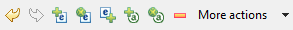
The toolbar icons are active depending on the selected node in the tree. Actions you can do comprise:
Undo and Redo the last action performed.
Add Child Element under the selected element.
Add (child) Wildcard Element under the selected element.
Add Sibling Element After the selected element.
Add Child Attribute to the selected element
Add Wildcard Attribute to the selected element.
Remove the selected node
More actions - besides other actions described above, you can especially Add Sibling Before or Add Sibling After
When building the XML tree from scratch (see Creating the Mapping - Designing New XML Structure ) why not make use of these tips saving mouse clicks and speeding up your work:
drag a port and drop it onto an element - you will create a Binding, see Creating the Mapping - Mapping Ports and Fields
drag a field and drop it onto an element - you will add a child element of the same name as the field
drag an available field (or even more fields) onto an element - you will create a subelement whose name is the field's name. Simultaneously, the element's content is set to
$portNumber.fieldName.drag one or more available ports and drop it onto an element with a Binding - you will create a Wildcard element whose Include will be set to
$portNumber.*combination of the two above - drag a port and a field (even from another port) onto an element with a Binding - the port will be turned to Wildcard element (Include=
$portNumber.*), while the field becomes a subelement whose content is$portNumber.fieldNamedrag an available port/field and drop it onto a Wildcard element/attribute - the port or field will be added to the Include directive of the Wildcard element/attribute. If it is a port, it will be added as $0.* (example for port 0). If it is a field, it will be added as $0.priceTotal (example for port 0, field priceTotal).
drag a port/field and drop it onto a property such as Include or Exclude (or any other excluding Input in Binding). That can be done either in the Content or Property panes - as a result, the property receives the value of the port/field. Multiselecting fields and dragging them works, too. Morevoer, if you hold down Ctrl while dragging, the port/field value will be added at the end of the property (not replacing it). Say your Include property currently contains e.g.
$0.*. Draggingfield1ofport $1and dropping it onto Include while holding Ctrl will produce this content:$0.*;$1.field1.
Every node you add can later be moved in the tree by a simple drag and drop using the left mouse button. That way you can re-arrange your XML tree any way you want. Actions you can do comprise:
drag an (wildcard) element and drop it on another element - the (wildcard) element becomes a subelement
drag an (wildcard) attribute and drop it on an element - the element now has the (wildcard) attribute
drag a text node and drop it on an element - the element's value is now the text node
drag a namespace and drop it on an element - the element now has the namespace
Removing nodes (such as elements or attributes) in the Mapping editor is also carried out by pressing Delete or right-clicking the node and choosing . To select more nodes at once, use Ctrl+click or Shift+click .
Any time during your work with the mapping editor, press Ctrl+Z to Undo the last action performed or Ctrl+Y to Redo it.
Creating the Mapping - Mapping Ports and Fields
In Creating the Mapping - Designing New XML Structure , you have learned how to design the output XML structure your data will flow to. Step two in working with the Mapping editor is connecting the data source to your elements and attributes. The data source is represented by ports and fields on the left hand side of the Mapping editor window. Remember the Field and Type columns cannot be modified as they are dependent on the metadata of the XMLWriter's input ports.
To connect a field to an XML node, click a field in the Field column, drag it to the right hand part of the window and drop it on an XML node. The result of that action differs according to the node type:
element - the field will supply data for the element value
attribute - the field will supply data for the atrribute value
text node - the field will supply data for the text node
advanced drag and drop mouse techniques will be discussed below
A newly created connection is displayed as an arrow pointing from a port/field to a node.
To map a port, click a port in the left hand side of the Mapping editor and drag it to the right hand part of the window. Unlike working with fields, a port can only be dropped on an element. Please note that dragging a port on an element DOES NOT map its data but rather instructs the element to repeat itself with each incoming record in that port. As a concequence, a new Binding pseudo-element is created, see picture below.
![[Note]](figures/note.png) | Note |
|---|---|
Binding an input port to the root element has some limitations. The root can only be bound in this way:
|
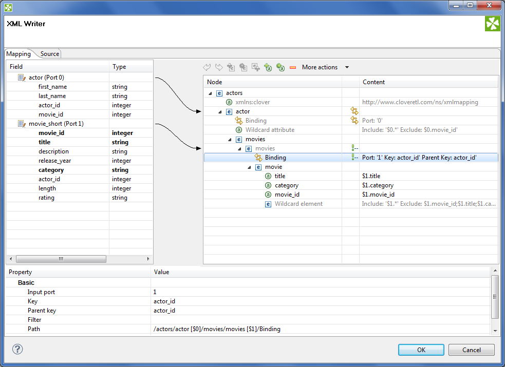
A Binding specifies mapping of an input port to an element. This binding drives the element to repeat itself with every incoming record.
Mouse over a Binding to have a tooltip displayed. The tooltip informs you whether the port data is being cached or streamed (affecting overall performance) and which port from. Moreover, in case of caching, you learn how your data would have to be sorted to enable streaming.
Every Binding comes with a set of properties:
Input port - the number of the port the data flows flows from. Obviously, you can always easily check which port a node is connected to looking at the arrow next to it.
Key and Parent key - the pair of keys determines how the incoming data are joined. In Key, enter names of the current element's available fields. In Parent key, enter names of fields available to the element's direct parent. Consequently, the data is joined when the incoming key values equal. Keep in mind that if you specify one of the pair of keys, you have to enter the other one too. To learn which fields are at disposal, click the "..." button located on the right hand side of the key value area. The Edit key window will open, enabling you to neatly choose parts of the key by adding them to the Key parts list. Naturally, you have to have exactly as many keys as parentKeys, otherwise errors occur.
If fields of key and parentKey have numerical values, they are compared regardless of their data type. Thus e.g. 1.00 (double) is considered equal to 1 (integer) and these two fields would be joined.
Note Keys are not mandatory properties. If you do not set them, the element will be repeated for every record incoming from the port it is bound to. Use keys to actually select only some of those records.
Filter - a CTL expression selecting which records are written to the output and which not. See Advanced Description for reference.
To remove a Binding, click it and press Delete (alternatively, right-click and select Remove or find this option in the toolbar).
Finally, a Binding can specify a JOIN between an input port and its parent node in the XML structure (meaning the closest parent node that is bound to an input port). Note that you can join the input with itself, i.e. the element and its parent being driven by the same port. That, however, implies caching and thus slower operation. See the following example:
Example 54.10. Binding that serves as JOIN
Let us have two input ports:
0 - customers (id, name, address)
1 - orders (order_id, customer_id, product, total)
We need some sort of this output:
<customer id="1">
		<name>John Smith</name>
		<address>35 Bowens Rd, Edenton, NC (North Carolina)</address>
		<order>
				<product>Towel</product>
				<total>3.99</total>
		</order>
		<order>
				<product>Pillow</product>
				<total>7.99</total>
		</order>
</customer>

<customer id="2">
		<name>Peter Jones</name>
		<address>332 Brixton Rd, Louisville, KY (Kentucky)</address>
		<order>
				<product>Rug</product>
				<total>10.99</total>
		</order>
</customer>
</programlisting>
You can see we need to join "orders" with "customer" on (orders.customer_id = customers.id). Port 0 (customers) is bound to the <customer> element, port 1 (orders) is bound to <order> element. Now, this is very easy to setup in the Binding pseudoattribute of the nested "order" element. Setting Key to "customer_id" and Parent key to "id" does exactly the right job.
Creating the Mapping - Using Existing XSD Schema
There is no need to create an XML structure from scratch if you already hold an XSD schema. In that case, you can use the schema to pre-generate the the XML tree. The only thing that may remain is mapping ports to XML nodes, see Creating the Mapping - Mapping Ports and Fields.
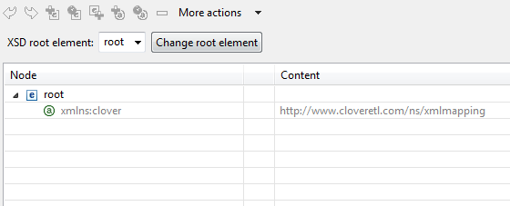
First of all, start by stating where your schema is. A full path to the XSD has to be set
in the XML Schema attribute. Second, open the Mapping editor
by clicking Mapping. Third, when in the editor,
choose a root element from the XSD and finally click Change root element
(see picture below). The XML tree is then automatically generated. Remember you still have
to use the cloudconnect namespace for the process to work properly.
Creating the Mapping - Source Tab
In the Source tab of the Mapping editor you can directly edit the XML structure and data mapping. The concept is very simple:
1) write down or paste the desired XML data
2) put data field placeholders (e.g. $0.field) into the source
wherever you want to populate an element or attribute with input data
3) create port binding and (join) relations - Input port, Key, Parent key
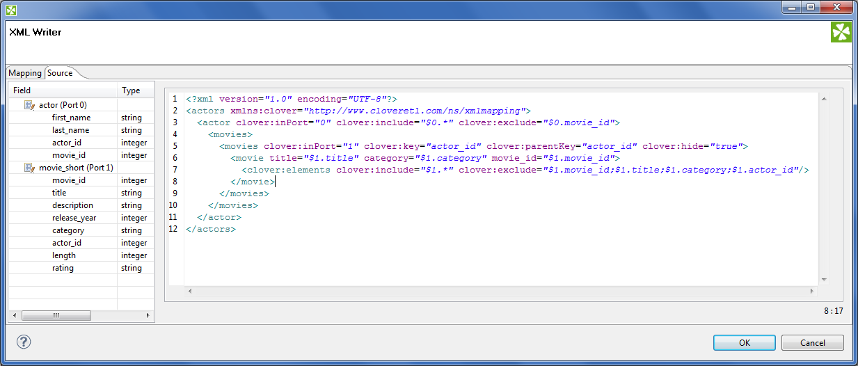
Here you are the same code as in the figure above for your own experiments:
<?xml version="1.0" encoding="UTF-8"?>
<actors xmlns:cloudconnect="http://www.cloudconnect.com/ns/xmlmapping">
  <actor cloudconnect:inPort="0" cloudconnect:include="$0.*" cloudconnect:exclude="$0.movie_id">
    <movies>
      <movies cloudconnect:inPort="1" cloudconnect:key="actor_id" cloudconnect:parentKey="actor_id"
      			cloudconnect:hide="true">
        <movie title="$1.title" category="$1.category" movie_id="$1.movie_id">
          <cloudconnect:elements cloudconnect:include="$1.*"
          		cloudconnect:exclude="$1.movie_id;$1.title;$1.category;$1.actor_id"/>
        </movie>
      </movies>
    </movies>
  </actor>
</actors>
Changes made in either of the tabs take immediate effect in the other one. For instance, if you
connect port $1 to an element called invoice in Mapping then switching to
Source, you will see the element has changed to: <invoice cloudconnect:inPort="1">.
Source tab supports drag and drop for both ports and fields located on the left
hand side of the tab. Dragging a port, e.g. $0 anywhere into the source code inserts the following:
$0.*, meaning all its fields are used. Dragging a field works the same way,
e.g. if you drag field id of port $2, you will get this code: $2.id.
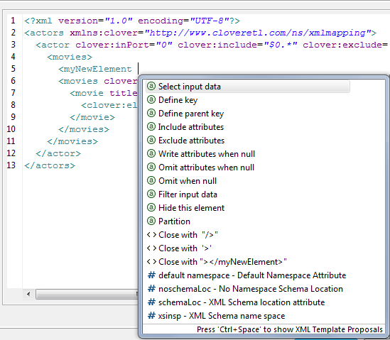
There are some useful keyboard shortcuts in the Source tab. Ctrl+F brings the Find/Replace dialog. Ctrl+L jumps quickly to a line you type in. Furthermore, a highly interactive Ctrl+Space Content Assist is available. The range of available options depends on the cursor position in the XML:
Inside an element tag - the Content Assist lets you automatically insert the code for Write attributes when null, Omit attributes when null, Select input data, Exclude attributes, Filter input data, Hide this element, Include attributes, Define key, Omit when null, Define parent key or Partition. On the picture below, please notice you have to insert an extra space after the element name so that the Content Assist could work.
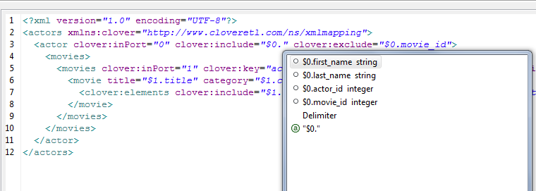
The inserted code corresponds to nodes and their properties as described in Creating the Mapping - Designing New XML StructureInside the "" quotes - Content Assist lets you smoothly choose values of node properties (e.g. particular ports and fields in Include and Exclude) and even add Delimiters. Use Delimiters to separate multiple expressions from each other.
In a free space in between two elements - apart from inserting a port or field of your choice, you can add Wildcard element (as described in Creating the Mapping - Designing New XML Structure ), Insert template or Declare template - see below.
Example 54.11. Insert Wildcard attributes in Source tab
First, create an element. Next, click inside the element tag, press Space, then press
Ctrl+Space
choose Include attributes. The following code
is inserted: cloudconnect:include="". Afterwards, you have to determine
which port and fields the attributes will be received from (i.e. identical activity to setting
the Include property in the Mapping tab). Instead of manually typing e.g.
$1.id,
use the Content Assist again.
Click inside the "" brackets, press
Ctrl+Space
and you will get a list
of all available ports. Choose one and press
Ctrl+Space
again.
Now that you are done with include press Space and then Ctrl+Space again. You
will see the Content Assist adapts to what you are doing and where you are. A new option has turned up:
Exclude attributes.
Choose it to insert cloudconnect:exclude="". Specifying its value corresponds
to entering the Exclude property in Mapping.
One last thing about the Source tab. Sometimes, you might need to work with the
$port.field syntax a little
more. Imagine you have port $0 and its price field. Your aim is to send
those prices to an element called e.g. subsidy. First, you establish a
connection between the port and the element. Second, you realize you would like to add the US dollar currency
right after the price figure. To do so, you just edit the source code like this
(same changes can be done in Mapping):
<subsidy>$0.price USD</subsidy>
However, if
you needed to have the "USD" string attached to the price for a reason, use the { } brackets
to separate the $port.field syntax from additional strings:
<subsidy>{$0.price}USD</subsidy>
If you ever needed to suppress the dollar placeholder, type it twice. For instance, if you want to print "$0.field" as a string to the output, which would normally map field data coming from port 0, type "$$0.field". That way you will get a sort of this output:
<element attribute="$0.field">
Templates and Recursion
A template is a piece of code that is used to insert another (larger) block of code. Templates can be inserted into other templates, thus creating recursive templates.
As mentioned above, the Source tab's Content Assist allows you to smoothly declare and use your own templates. The option is available when pressing Ctrl+Space in a free space in between two elements. Afterwards, choose either Declare template or Insert template.
The Declare template inserts the template header. First, you need to enter the template name. Second, you fill it with your own code. Example template could look like this:
<cloudconnect:template cloudconnect:name="templCustomer">
<customer>
	<name>$0.name</name>
	<city>$0.city</city>
	<state>$0.state</state>
</customer>
</cloudconnect:template>
To insert this template under one of the elements, press Ctrl+Space and select Insert template. Finally, fill in your template name:
<cloudconnect:insertTemplate cloudconnect:name="templCustomer"/>
In recursive templates, the insertTemplate tag appears inside the template
after its potential data. When creating recursive structures, it is crucial to
define keys and parent keys. The recursion then continues as long as there are matching
key and parentKey pairs. In other words, the recursion depth
is dependent on your input data. Using filter can help to get rid of
the records you do not need to be written.